n the chemical processing industry, there are numerous types of heat exchanger devices. The types of exchangers can be classified by the duty that they perform, surface compactness, construction features, flow arrangements, and others. In general, a heat exchanger can fall into one of these processing categories:
1. No Phase Change
- Liquid to Liquid heat transfer
- Liquid to Gas heat transfer
- Gas to Gas heat transfer
- Condensing a vapor with a liquid or gas service fluid
- Vaporizing a liquid with a liquid, gas, or condensing fluid
Heat exchangers can also be broken down into the following two types of mechanical geometries:
- Shell and Tube Heat Exchangers
- Compact and Extended Surface Heat Exchangers
Approximately 70-80% of the heat exchanger market is dominated by the shell and tube type heat exchanger. It is largely favored due to its long performance history, relative simplicity, and its wide temperature and pressure design ranges. We will explore this technology in further detail later.
The second category mentioned, compact and extended surface heat exchangers, play a smaller role in the chemical processing industry. Some of the available technologies that fit into this category are the plate and frame heat exchanger, finned tube heat exchangers, spiral heat exchangers, fin-fan heat exchangers, and many others.
The second category mentioned, compact and extended surface heat exchangers, play a smaller role in the chemical processing industry. Some of the available technologies that fit into this category are the plate and frame heat exchanger, finned tube heat exchangers, spiral heat exchangers, fin-fan heat exchangers, and many others.
Compact Heat Exchanger Technologies
The plate exchanger, shown below, consists of corrugated plates assembled into a frame. The hot fluid flows in one direction in alternating channels while the cold fluid flows in true countercurrent flow in the opposite alternating channels. The fluids are directed into their proper channels either by a rubber gasket or a weld depending on the type of exchanger chosen.
Traditionally, plate and frame exchangers have been used almost exclusively for liquid to liquid heat transfer. Today, many variations of the plate technology have proven useful in applications where a phase change occurs as well. This includes condensing duties as well as vaporization duties. Plate heat exchangers are best known for having overall heat transfer coefficients (U-values) in excess of 3-5 times the U-value in a shell and tube designed for the same service.
Plate exchangers can be especially attractive when more expensive materials of construction are required. The significantly higher U-value results in far less area for a given application, thus a lower purchased and installed cost due to its relatively small size. The higher U-values are gained by inducing extremely high wall shear on the plate surface. The best way to think of a plate heat exchanger is that it is essentially a static mixer that happens to transfer heat very well. The plate exchanger, by virtue of its high wall shear stress also minimizes fouling very well.
Typical plate thicknesses range from 0.40 mm to 0.60 mm and passage channel openings can range from 1.5 mm up to 11.0 mm depending on the application and required design pressure (the larger the opening, the lower the design pressure available). These small passages also restrict the size of solids that can be successfully passed through the exchanger.
Perhaps the biggest advantage of the plate and frame heat exchanger, and a situation where it is most often used, is when the heat transfer application calls for the cold side fluid to exit the exchanger at a temperature significantly higher than the hot side fluid exit temperature. This situation is best explained with another set of T-Q diagrams:
Duty 1 shown above is easily accomplished in a single and tube heat exchanger.
Duty 2 shows a severe "temperature cross" or the cold side fluid exiting higher than the hot side fluid. This would require several shell and tube exchangers in series due to the lack of purely counter-current flow. On the other hand, this duty is easily accomplished in a single plate and frame heat exchanger.
Finned Tube Heat Exchanger
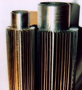
Finned tube heat exchangers are commonly used to transfer heat between a gas and liquid. The tubes used in these units are equipped with fins that extend outward from the tubes as shown in Figure 10.
The fins on the tubes allow for a much larger surface area to be packed into a small volume. This is especially important when transferring heat to or from a gas as gasses have extremely low heat transfer coefficients (meaning that large amounts of area are required).
The fins on the tubes allow for a much larger surface area to be packed into a small volume. This is especially important when transferring heat to or from a gas as gasses have extremely low heat transfer coefficients (meaning that large amounts of area are required).
Fin Fan Heat Exchanger
Fin-fan heat exchangers are designed to use air to cool process fluids. Think of them as a giant radiator. The process fluid is passed through the coils and a fan helps pull air over the outside surface to promote cooling. These units again must provide a very large surface area to make up for the poor heat transfer of the air.
Shell and Tube Heat Exchanger
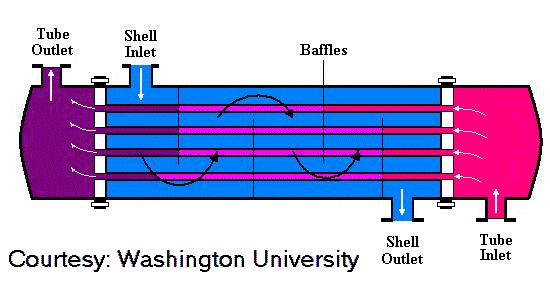
Shell and tube heat exchangers are known as the work-horse of the chemical process industry when it comes to transferring heat. These devices are available in a wide range of configurations as defined by the Tubular Exchanger Manufacturers Association (TEMA, www.tema.org). In essence, a shell and tube exchanger is a pressure vessel with many tubes inside of it. One process fluids flows through the tubes of the exchanger while the other flows outside of the tubes within the shell. The tube side and shell side fluids are separated by a tube sheet.
The shell and tube type is usually indicated as a three (3) letter code from the TEMA specifications as shown in figure below.
The shell side of a shell and tube exchanger usually contains baffles as shown above to direct the shell side flow around the tubes to enhance heat transfer. As you can see, shell and tube exchangers can be configured for liquid-liquid, gas-liquid, condensing, or vaporizing heat transfer.
The tubes can be a different material than shell and the shell can either be cladded or of solid construction. It's impossible to go over all of the mechanical details of the shell and tube here, but this should provide you with a general overview of the construction. There are numerous other sources of information freely available on these types of units.
The tubes and shell can be designed for a variety of design temperatures and pressures. The thermal design of shell and tube heat exchangers is often performed by vendors. The process engineer generally completes a TEMA specification sheet and submits it to vendors for bids. If you're interested in more details on the thermal design aspects of shell and tube heat exchangers, you can visit Wolverine Engineering's website at:
http://www.wlv.com/p...ok/databook.pdf
Understanding the basics of industrial heat transfer will help you better understand opportunities for cost savings in your plant. With energy prices showing no sign of declining, a good basis in heat transfer will help you calculate just how much you can save by installing a new heat exchanger in your plant. With the use a T-Q diagram and a basic understanding of the equipment available to you, making the right choice in heat transfer equipment can yield results for years to come.
Source:
www.cheresources.com


Nice information, There is obviously a lot. Your points are very valuable and knowledgeable. Thanks for sharing this great blog with us.
ReplyDeleteImpact Cooling Solutions
Thanks for Sharing Brief Overview of Heat Exchanger.
ReplyDeleteplate heat exchangers manufacturers india.
I admire this article for the well-researched content and excellent wording. I got so involved in this material that I couldn’t stop reading. I am impressed with your work and skill. Thank you so much. you can replace a heat exchanger
ReplyDelete